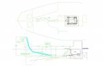
first my old system see attached (pic 02,52,33)-had 60 hp perkins #4203 repowering with Beta 50hp.
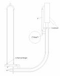
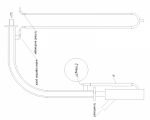
next plan A system (see attached drawing) with two waterlocks drawing.
even with the two waterlocks I don't think they can handle the volume of water in the 9'6 hose. (This is my only waterlock option with my limited space available) my old system makes since to me as there is no way watercan travel from the port side to the STB side muffler. but is a 90 degree bend and aprox 3' rise to much back pressure?
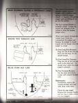
I think that your standpipe arrangement as used on the old engine should work just fine. I would definetely build a new one and also include a new flex section between the engine and the standpipe. It won't hurt to fit an anti siphon valve in the water line between the heat exchanger and the water injection point of the standpipe as well. This will also be mounted above the waterline.
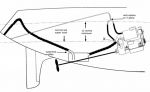
I have drawn in an anti siphon loop as you suggested.
but I have a mystery, its been 10 yrs since I pulled the motor and I don't remember what the 1/2" fitting on the upper fitting of the water jacket went to, any thoughts
Is it possible that the 1/2" fitting went to the stuffing pox for cooling?
This fitting is not really needed for the exhaust system to function.
The anti-siphon valve as you have drawn it wont work.
I am confused "fit an anti siphon valve in the water line between the heat exchanger and the water injection point"
could you draw in where it should be.
the stuffing box is not water cooled, could it be a secondary supply form the heat exchanger line or from the heat exchanger for the velvet transmission ?
If you actually study the drawing that I posted and the one from our website you will see that the water exits the heat exchanger, runs up to the anti siphon valve and then down to the water injection point on the exhaust water injection elbow.
Stanley, it is very obvious now. I didn't understand that for the anti siphon to work it needs to be part of and wholly contained in the water supply line.
thank you again for helping me with my exhaust system and mostly bearing with me .oh and I am thinking that the 1/2" fitting went the hot water tank.